Setup/Requirements
This page is intended as a comprehensive resource for setting up the MozART Installation. From here, you should be able to set up the installation with reasonable ease, in addition to troubleshoot some issues you may encounter throughout the setup process.
- Frame Setup
- Kinect Setup
- Projector Setup
- Speaker Setup + Requirements
- Ableton Live Setup
- Processing Setup
Page Contents:
Frame Setup
The Frame Setup Guide is available in the following pdf: PDF
Kinect Calibration
Ensuring that the Kinect is setup correctly is vital to the success of MozART, and therefore great care must be taken to calibrate it correctly. The Kinect must be placed on a tripod approximately 1.5 metres high. Different tripods can mean that the positioning could be different, but the tripod used in the project required the two front legs to be placed directly behind the back-supporting beam on the floor.
The easiest way to get the correct calibration on the Kinect is to run the master sketch, and adjust the threshold by clicking the up or down arrow keys until the frame and spandex starts to be picked up. The bottom of the frame should be at the bottom of the sketch window, with approximately half of the sketch window being empty above the frame itself. The Kinect may also need to be tilted up or down to ensure that it is as flat as possible in line with the spandex, such that the depth at the top and the bottom of the spandex are picked up at the same time. Once everything is calibrated, adjust the threshold so that no blobs are being picked up, but that a normal push on the canvas will result in a medium sized blob. Testing multiple blobs at the same time to check whether they render as separate blobs or merge together is also useful in determining the correct threshold. With the current setup, the threshold value is typically around 1750.
Projector Calibration
To begin, place the projector box roughly 5cm behind the back support beam of MozART. If the projector doesn't fully cover the screen from this distance, slide the box back. Ideally there should be some of the projection the the sides of the frame, with minimal shadow on the bottom border of the spandex. There should also be a tiny portion of the image which overshoots the top of the frame. This is ideal, as this area will be where the taskbar and window frame will sit, which we do not want to show on the screen.
To ensure that the MozART experience is as seemless as possible, it's recommended that the taskbar be at the top of the screen and set to auto-hide (as pictured below).
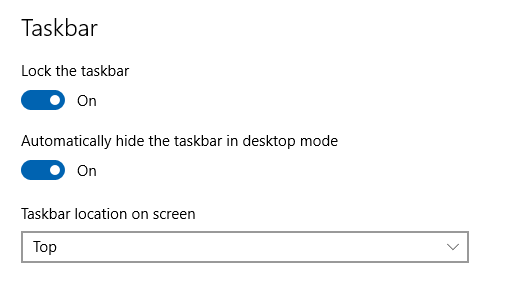
Ideally, this setup should ensure that only the MSAFluid window is displayed on the spandex screen.
Troubleshooting:
If the image appears tilted, check that the box and projector are both parallel to the rear support beam of MozART. If the image is still tilted, check that the feet of the projector (located at the front centre, and rear left and right corners of the device) are all set to the same height. If neither of these steps fix this problem, press the button on the projector immediately above the circular enter button. This will open a menu which will allow you to manipulate the image a reasonable amount.
If the image appears blurry, adjust the keystone until the image comes into focus. This may also be an issue with the computer's resolution. Take note of the resolution that the computer was set to before adjusting the image, as it may have been set to that particular size for the MSAFluid canvas.
Speaker Requirements + Setup
Setting up the audio component of the MozART device can vary greatly depending on the context. As MozART is heavily dependant on the users being able to clearly hear the sounds being generated, it is recommended that it either be connected directly to studio monitors, or into a sound system. It has been noted that audio problems may occur if the computer is directly plugged into the audio system of your choice. As such, we recommend sending the signal through an amplifier before it reaches the speakers.
-
Before you begin:
- Ableton Live will not be able to find the speakers if they are connected after the application is opened. Save yourself a headache and test that the device is working using Windows' sound control panel, before setting up Live.
- Speakers must be the last device turned on and the first device turned off. This is to ensure that there is little to no static in the signal which may cause the speakers to blow out while setting up.
- If possible, set the amplifier gain to -inf dB (may also be written as 0, depending on device) before beginning. Again, this is largely to ensure that you don't blow out the speakers.
Connecting to a Mixer (UQ Touch Ensemble)
-
Audio Devices required:
- Two Direct Boxes (We used these ones)
- 3.5mm Male to twin XLR Male cable
- Two Female XLR to Male XLR cables

Notes on this layout:
Before beginning, it's recommended that you check with the audio engineer what kind of cables the mixer requires. They also may be able to source the audio devices (or suitable alternatives) that you need.
Connecting to Studio Monitors (Standalone Performance)
-
Audio Devices required:
- A small headphone amplifer (We used this one)
- Auxillary cable (3.5mm Male to 3.5mm Male)
- Two 3.5mm Female to 6.5mm Male adaptors
- 3.5mm Male to twin XLR Male cable
- Two powered studio monitors (With XLR input)

Notes on this layout:
You may need to use a second powerboard for this setup, as both the speakers and the amplifier require AC power.
Before you power anything on, double check that the auxillary cable (with 6.5mm adaptor) from the computer is plugged into the input port on the amplifier, and the output port of choice is set to 0. Again, this is just a precaution to avoid damaging the speakers.
Ableton Live Setup
Download the Live 9 project files we used for MozART here
Before you begin:
You will need to ensure that you have installed both the ASIO4All driver and loopMIDI.In order to connect the Processing Sketch to Ableton Live, you will need to set up loopMIDI as below:
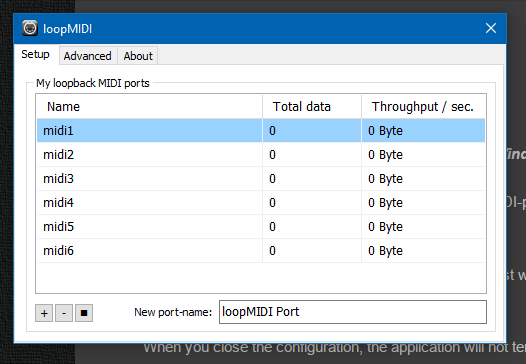
Calibrating MIDI Ports
For an indepth guide on Routing and I/O in Live, click here.Step 1) Within Live, open the Preferences menu (ctrl +). Select the Link/MIDI tab and set as below:
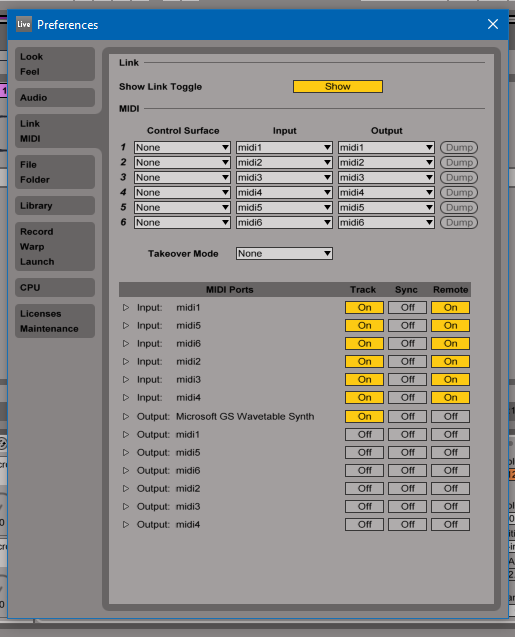
Once these settings are correct, close the Preferences menu.
Step 2) Ensure that you are both in Session View and have the In/Out section toggled on. To switch between Session and Arrangement view, press tab. To toggle In/Out, click the I.O button on the bottom right of the window.
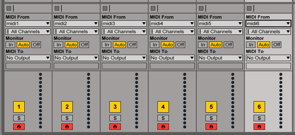
Step 3) For each of the six instrument channels, select the respective loopMIDI device in the MIDI From drop down menu. You don't need to change any other settings in this section, though you can change Monitor to "In" if Live appears to be sending data back to the loopMIDI device causing it to slow down.
Step 4) Finally, arm each MIDI device by ctrl clicking on each track's arm button.
After following these steps, your Session should look like this:
Mapping MIDI
If you are using the project files as linked above, you can skip this process, as the document is already set up for the loopMIDI devices.Before you begin, open setMIDIMaps.pde which should be contained in a folder titled setMIDIMaps. This particular sketch spoofs the MIDI data which would be sent to Live during a MozART performance allowing you to accurately map particular data points to variables within Live. If you are building the instrument from scratch it is strongly recommended that you highlight values that you wish to change by placing the devices in either an instrument rack or an effect rack, with each particular value mapped to a macro. To find out more about Instrument, Drum and Effect Racks, click here.
To begin, select the first instrument you would like to map. Then click the MIDI button in the top right corner of Live to start mapping MIDI devices. You will need to stop MIDI mapping when you switch instruments, as Live might lose previously saved mappings.
To map a device, click on the macro you wish to control, then click the respective parameter within the setMIDIMaps program. You will need to repeat this process for each individul instrument track, so pay careful attention to which instrument you are controlling.
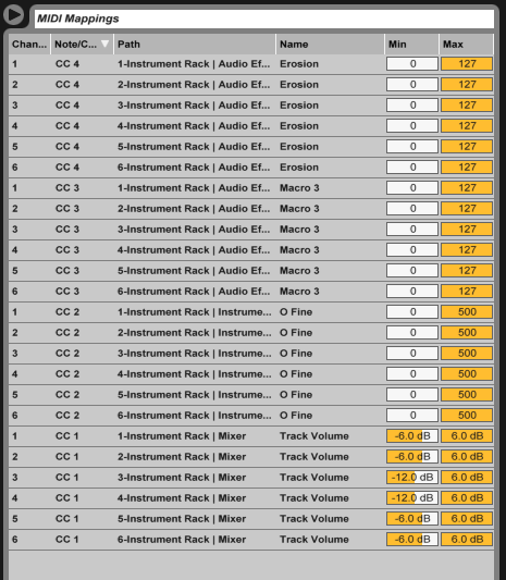
If you ever get lost while mapping, you can refer to the fraction next to the macro you just mapped. The numerator signifies which MIDI device is going to control that particular data point, while the denominator represents the MIDI CC channel. The CC channels in setMIDIMaps are under the following names:
- CC 1: Map Depth
- CC 2: Map Lifespan
- CC 3: Map Speed
- CC 4: Map X-axis
Once you're finished you should have a list of mappings similar to this:
Troubleshooting
If there is a massive delay between sending MIDI to Live and it generating sound, you may need to change the audio drivers from MME/DirectX to ASIO. If Live isn't generating sound while on the ASIO drivers, ensure that you followed Before You Begin in the Speaker Setup section. If you have, and Live is still not playing audio, open ASIO4All settings and turn off every device except the speakers. Image-Line has a reasonably good resource which explains the ASIO4All interface.If the Audio is crackling, there may be an issue with the latency within Live. To fix this, you will need to fiddle with the input buffer size to reach a point where the audio isn't massively delayed as well as not crackling. These are Ableton's suggestions for optimising audio quality with MIDI
Processing Setup
Any version of Processing 2.x can be used to run this project. Please note that neither Processing 1.x or 3.x are compatible, and will result in several problems occurring with the visuals.
Please download Processing 2 from the following link: https://processing.org/download/ The most recent version is 2.2.1, released on 19th of May 2014.
Instructions to install the correct Processing libraries can be found here: https://github.com/UQMozart/UQMozART-Interactive-Installation